Home
› Logic Flow Diagram Symbols / Flow Chart | Siri's Blog / The logical functions in these diagrams are represented by their respective symbols whereas the blocks are used to represent the complex logic circuit.
Logic Flow Diagram Symbols / Flow Chart | Siri's Blog / The logical functions in these diagrams are represented by their respective symbols whereas the blocks are used to represent the complex logic circuit.
Logic Flow Diagram Symbols / Flow Chart | Siri's Blog / The logical functions in these diagrams are represented by their respective symbols whereas the blocks are used to represent the complex logic circuit.. Sankey diagrams, a specific type of flow diagram, uses the width of an arrow or stripe to show the proportion of a quantity. A logic gate is a device that can perform one or all of the boolean logic operations and, nand, nor, not, or, xnor, and xor. Click here for special instructions on using our stencils with microsoft visio 2013. It is obvious that when the basic logic symbols are understood, figuring out how the pump operates and how it will respond to various combinations of inputs using the logic diagram is fast and easy, as compared to laboriously tracing through the relays and contacts of the schematic. Logic flowchart symbols the following symbols are used on a logic flowchart:
Figure 1 presents a schematic for a large pump, and figure 2 shows the same pump circuit using only logic gates. The logic associated with starting and stopping the motor is usually included in p&id diagrams. It is obvious that when the basic logic symbols are understood, figuring out how the pump operates and how it will respond to various combinations of inputs using the logic diagram is fast and easy, as compared to laboriously tracing through the relays and contacts of the schematic. Sankey diagrams, a specific type of flow diagram, uses the width of an arrow or stripe to show the proportion of a quantity. As discussed that flow chart is basically the combination of the different symbols and each symbol in the flow chart has its own functionality.
Logic Flow Diagram Symbols - Wiring Diagram Schemas from www.researchgate.net Typically, a flowchart shows the steps as boxes of various kinds, and their order by connecting them with arrows. Here, you will see the 5 flowchart symbols that are very popular and commonly used in almost every flowchart. The older logic negation indicator means that the external 0 state produces the internal 1 state. Add a decision diamond symbol from the autoshape menu. The logical functions in these diagrams are represented by their respective symbols whereas the blocks are used to represent the complex logic circuit. Ladder logic symbols are the fundamental programming components used in ladder diagrams. Need more help with your hsc study? Logic negation may be used in pure logic diagrams;
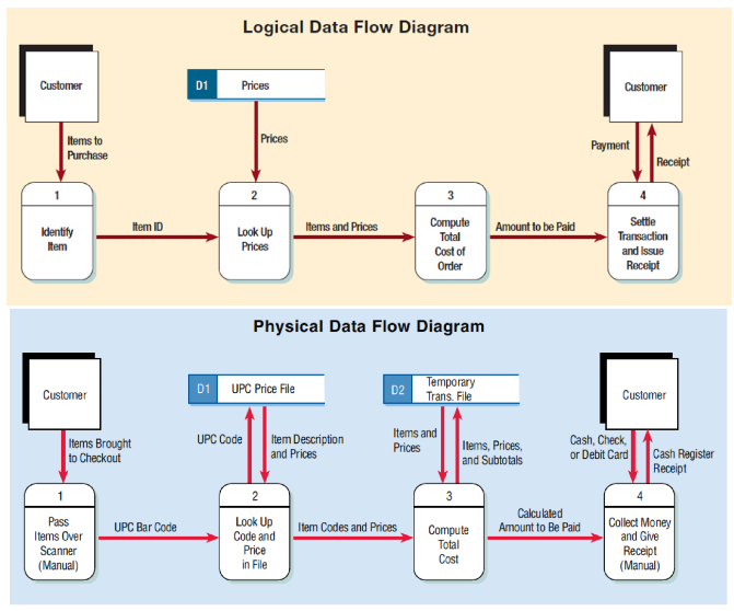
A data flow diagram (dfd) maps out the flow of information for any process or system.
As discussed that flow chart is basically the combination of the different symbols and each symbol in the flow chart has its own functionality. Data flow diagrams are composed of four elements: Flow meter symbol in p id Yourdon and coad and gane and sarson. Stretch the diamond to enclose the words in the text box. The internal 1 state means the active state. Used to indicate the 'or' logic. A relay logic circuit is a schematic diagram which shows various components, their connections, inputs as well as outputs in a particular fashion. The logic associated with starting and stopping the motor is usually included in p&id diagrams. Sankey diagrams, a specific type of flow diagram, uses the width of an arrow or stripe to show the proportion of a quantity. Place the diamond over the text box. Need more help with your hsc study? Direction symbol arrows indicating the flow of true or false result.
Besides the logic diagram tool, we've put together some logic diagram templates to help. In physical dfds, the processes are software programs, manual procedures or. In relay logic circuits, the contacts no and nc are used to indicate normally open or normally close relay circuit. No matter you want a logic diagram tool for teaching, or a logic circuit software for engineering purposes, our online logic diagram creator just works perfectly. Sankey diagrams, a specific type of flow diagram, uses the width of an arrow or stripe to show the proportion of a quantity.
Logical Data Flow Diagram Example - Atkinsjewelry from media.cheggcdn.com Flow meter symbol in p id Before you write code, you can use a flowchart to create a diagram of the steps in your algorithm and evaluate any potential issues with your logic. Flowchart tutorial (with symbols, guide and examples) a flowchart is simply a graphical representation of steps. Besides the logic diagram tool, we've put together some logic diagram templates to help. Generally, the isa symbology tends to be better suited for piping and instrumentation diagrams (p&ids), while the sama diagrams are better suited to indicate complex logic functions and control. These symbols are given as under. Ladder logic symbols are the fundamental programming components used in ladder diagrams. Place the diamond over the text box.
It is obvious that when the basic logic symbols are understood, figuring out how the pump operates and how it will respond to various combinations of inputs using the logic diagram is fast and easy, as compared to laboriously tracing through the relays and contacts of the schematic.
As discussed that flow chart is basically the combination of the different symbols and each symbol in the flow chart has its own functionality. To make a flowchart in smartdraw, you start by picking one of the flowchart templates included and add. But the elements represent different perspectives in logical dfds than in physical dfds. · termination — a symbol used to indicate the start and finish of the flowchart. Start and end symbols, represented as lozenges, ovals or rounded rectangles, usually containing the word start or end, or another phrase signaling the start or end of a process, such as submit enquiry or receive product. Direction symbol arrows indicating the flow of true or false result. Ladder logic symbols are the fundamental programming components used in ladder diagrams. These symbols are given as under. In order to tie the external 1 and 0 logic states to the levels high (h) and low (l), a statement of whether positive logic (1 = h, 0 1 l Figure 1 presents a schematic for a large pump, and figure 2 shows the same pump circuit using only logic gates. The term functional in this context is different from its use in functional programming or in mathematics, where pairing functional with flow would be ambiguous. A typical flowchart from older computer science textbooks may have the following kinds of symbols: Typically, a flowchart shows the steps as boxes of various kinds, and their order by connecting them with arrows.
Data flow diagrams are composed of four elements: In relay logic circuits, the contacts no and nc are used to indicate normally open or normally close relay circuit. Start and end symbols, represented as lozenges, ovals or rounded rectangles, usually containing the word start or end, or another phrase signaling the start or end of a process, such as submit enquiry or receive product. As discussed that flow chart is basically the combination of the different symbols and each symbol in the flow chart has its own functionality. The older logic negation indicator means that the external 0 state produces the internal 1 state.
63 INFO FLOWCHART LOGIC PDF DOC PPT DOWNLOAD XLS - Flowchart from lh5.googleusercontent.com Ladder logic symbols are the fundamental programming components used in ladder diagrams. The flowchart shows the steps as boxes of various kinds, and their order by connecting the boxes with arrows. Logic flowchart symbols the following symbols are used on a logic flowchart: Set the diamond fill color to none. External entities, processes, data stores and data flows. As discussed that flow chart is basically the combination of the different symbols and each symbol in the flow chart has its own functionality. Used to indicate the logic 'and'. To make a flowchart in smartdraw, you start by picking one of the flowchart templates included and add.
In sumo logic, flow diagrams can show the flow within a distributed system, for example, or can be used to see how customers flow through your website via states, which are triggered by log events.
Click here for special instructions on using our stencils with microsoft visio 2013. To make a flowchart in smartdraw, you start by picking one of the flowchart templates included and add. For example, in logical dfds, the processes are business activities; What are the symbols used in data flow diagrams (dfd)? A typical flowchart from older computer science textbooks may have the following kinds of symbols: It is obvious that when the basic logic symbols are understood, figuring out how the pump operates and how it will respond to various combinations of inputs using the logic diagram is fast and easy, as compared to laboriously tracing through the relays and contacts of the schematic. Flow meter symbol in p id Need more help with your hsc study? Ladder logic symbols are the fundamental programming components used in ladder diagrams. The logic gate software has all the logic symbols you need to design any kind of logic model. Add a decision diamond symbol from the autoshape menu. To avoid any mistakes you should know about the flowchart symbols. Flowchart symbols (8.3.13) a flowchart is a type of diagram that represents an algorithm, workflow or process, showing the steps as boxes of various kinds, and their order by connecting them with arrows.