Home
› Wire A Switch Diagram : Wiring Lighting Fixtures | Way Switch Diagram (Power into Light) - (pdf, 75kb) | 3 way switch ... : The black hot connection is broken to turn the light on/off, the white neutral connection completes the circuit.
Wire A Switch Diagram : Wiring Lighting Fixtures | Way Switch Diagram (Power into Light) - (pdf, 75kb) | 3 way switch ... : The black hot connection is broken to turn the light on/off, the white neutral connection completes the circuit.
Wire A Switch Diagram : Wiring Lighting Fixtures | Way Switch Diagram (Power into Light) - (pdf, 75kb) | 3 way switch ... : The black hot connection is broken to turn the light on/off, the white neutral connection completes the circuit.. As you see in the 2 way switch diagram below, you will find that the phase/live is. Pick the diagram that is most like the scenario you are in and see if you can wire your switch! This page contains wiring diagrams for four different types of household lamps. This wiring diagram applies to several switches with the only difference being the color of the lights. For the instructions below, we're assuming that you are converting an.
There are 2 rows of pins, 3 pins in each row, the middle one is the common terminal, corresponding to the two left and right pins, one is normally open and the other is normally closed. A wiring diagram is a simplified conventional pictorial representation of an electrical circuit. Unlike a pictorial diagram, a wiring diagram uses abstract or simplified shapes and lines to show components. For example, a switch will be a break in the line with a line at an angle to the wire. The toggle switch is a switch that can play crucial switching roles in circuits.
Hampton Bay 3 Speed Ceiling Fan Switch Wiring Diagram Download from wholefoodsonabudget.com This is the same connection as. Learn how to wire a single pole switch. If you are going to install a new one then go for three wire control methods. Two way switching schematic wiring diagram (3 wire control). How to wire a two way switch made easy below is the way i like to do it. The wire colors shown in the switch diagrams below are not the only ones possible. Most symbols used on a wiring diagram look like abstract versions of the real objects they represent. This wiring diagram applies to several switches with the only difference being the color of the lights.
Below the diagram, you will find easy to follow.
This is a diagram of a switch with a neutral. Notice on the wiring diagram that of the 10 prongs (spade connectors, called termianls) on the back, four 4 make the rocker switch lights function, while the remaining six are used for the. The wire colors shown in the switch diagrams below are not the only ones possible. It shows the components of the circuit as simplified shapes, and the power and signal connections between the devices. This page contains wiring diagrams for four different types of household lamps. For the instructions below, we're assuming that you are converting an. Below the diagram, you will find easy to follow. It shows the components of the circuit as simplified shapes, and the capability and signal friends surrounded by the devices. Explanation of wiring diagram #1. Switch wiring shows the power source (power in) starts at the switch box. They are some of what you may encounter, not necessarily how it should be done to current code. This might seem intimidating, but it does not have to be. Level beginner description power (a hot and a neutral) is fed to the switch with 1.
This is a diagram of a switch with a neutral. The black hot connection is broken to turn the light on/off, the white neutral connection completes the circuit. Level beginner description power (a hot and a neutral) is fed to the switch with 1. This page contains wiring diagrams for four different types of household lamps. Depending on the current setup and the fixture you're wiring the switch into, you may also need some additional wire nuts to create secure connections to your home's existing wiring.
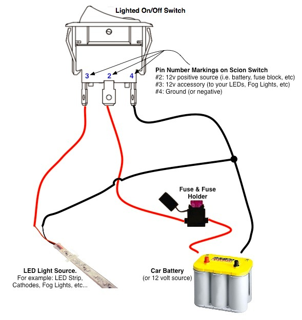
On/Off Switch & LED Rocker Switch Wiring Diagrams | Oznium from lh4.googleusercontent.com Here are a few that may be of interest. Explanation of wiring diagram #1. For example, a switch will be a break in the line with a line at an angle to the wire. Below is the wiring schematic diagram for connecting a spst toggle switch How to wire a single pole light switch, in this video we look at how a single pole light switch works and the different ways to wire a light circuit. They are some of what you may encounter, not necessarily how it should be done to current code. Switch wiring shows the power source (power in) starts at the switch box. In a switch loop the hot and neutral wires arrive at the light fixture before reaching the switch.
Armed with a wiring diagram and the necessary tools, install the boxes that house the switches.
I've had a number of people ask me about a wiring diagram, as the photos may not be enough on their own. They are some of what you may encounter, not necessarily how it should be done to current code. How to wire a two way switch made easy below is the way i like to do it. The wire colors shown in the switch diagrams below are not the only ones possible. With 9 different single pole switch wiring methods including switch fed, light fed, half switched receptacles the most simple and common method of wiring a single pole switch. A wiring diagram is a simplified conventional pictorial representation of an electrical circuit. In fig 2, different connection and wiring diagrams are shown for a two pole, single phase manual changeover switch. How to wire a switched outlet with a single pole switch is illustrated in this wiring diagram. Unlike a pictorial diagram, a wiring diagram uses abstract or simplified shapes and lines to show components. Below is the wiring schematic diagram for connecting a spst toggle switch The schematic is nice and simple to visualise the principal of how this works but is little help when it coms to actually wiring this up in real life!! A wiring diagram is a visual representation of components and wires related to an electrical connection. Pick the diagram that is most like the scenario you are in and see if you can wire your switch!
They are some of what you may encounter, not necessarily how it should be done to current code. The upper portion of the changeover fig 4 shows that how to wire a four poles, three phase manual changeover switch to the main distribution board. Pick the diagram that is most like the scenario you are in and see if you can wire your switch! The schematic is nice and simple to visualise the principal of how this works but is little help when it coms to actually wiring this up in real life!! A wiring diagram is a simplified conventional pictorial representation of an electrical circuit.
Insteon 2 Way Switch Wiring Diagram from wiringall.com This is a diagram of a switch with a neutral. How to wire a two way switch made easy below is the way i like to do it. There are 2 rows of pins, 3 pins in each row, the middle one is the common terminal, corresponding to the two left and right pins, one is normally open and the other is normally closed. As you see in the 2 way switch diagram below, you will find that the phase/live is. They are some of what you may encounter, not necessarily how it should be done to current code. Unlike a pictorial diagram, a wiring diagram uses abstract or simplified shapes and lines to show components. It shows the components of the circuit as simplified shapes, and the power and signal connections between the devices. A wiring diagram is a simplified conventional pictorial representation of an electrical circuit.
The schematic is nice and simple to visualise the principal of how this works but is little help when it coms to actually wiring this up in real life!!
Level beginner description power (a hot and a neutral) is fed to the switch with 1. 6 p switch schematic diagram and connection method: Depending on the current setup and the fixture you're wiring the switch into, you may also need some additional wire nuts to create secure connections to your home's existing wiring. This might seem intimidating, but it does not have to be. Wiring a single pole switch. Below the diagram, you will find easy to follow. The black hot connection is broken to turn the light on/off, the white neutral connection completes the circuit. A wiring diagram is a simplified conventional pictorial representation of an electrical circuit. How to wire a two way switch made easy below is the way i like to do it. This article explains a 3 way switch wiring diagram and step how to wire three way light switch electrical circuit we have to discuss about what are the three ways for wiring diagram as discussed below and how to connect all the lights and what are the different techniques to join such switches to. Explanation of wiring diagram #1. If you are going to install a new one then go for three wire control methods. Notice on the wiring diagram that of the 10 prongs (spade connectors, called termianls) on the back, four 4 make the rocker switch lights function, while the remaining six are used for the.